Unmanned Vehicle Experimental Platform Project
Introduction
🌞 Aims:
- The main goal of this project is to design a versatile unmanned vehicle experimental platform that can be used for the development and validation of algorithms such as SLAM, path planning, and object detection.
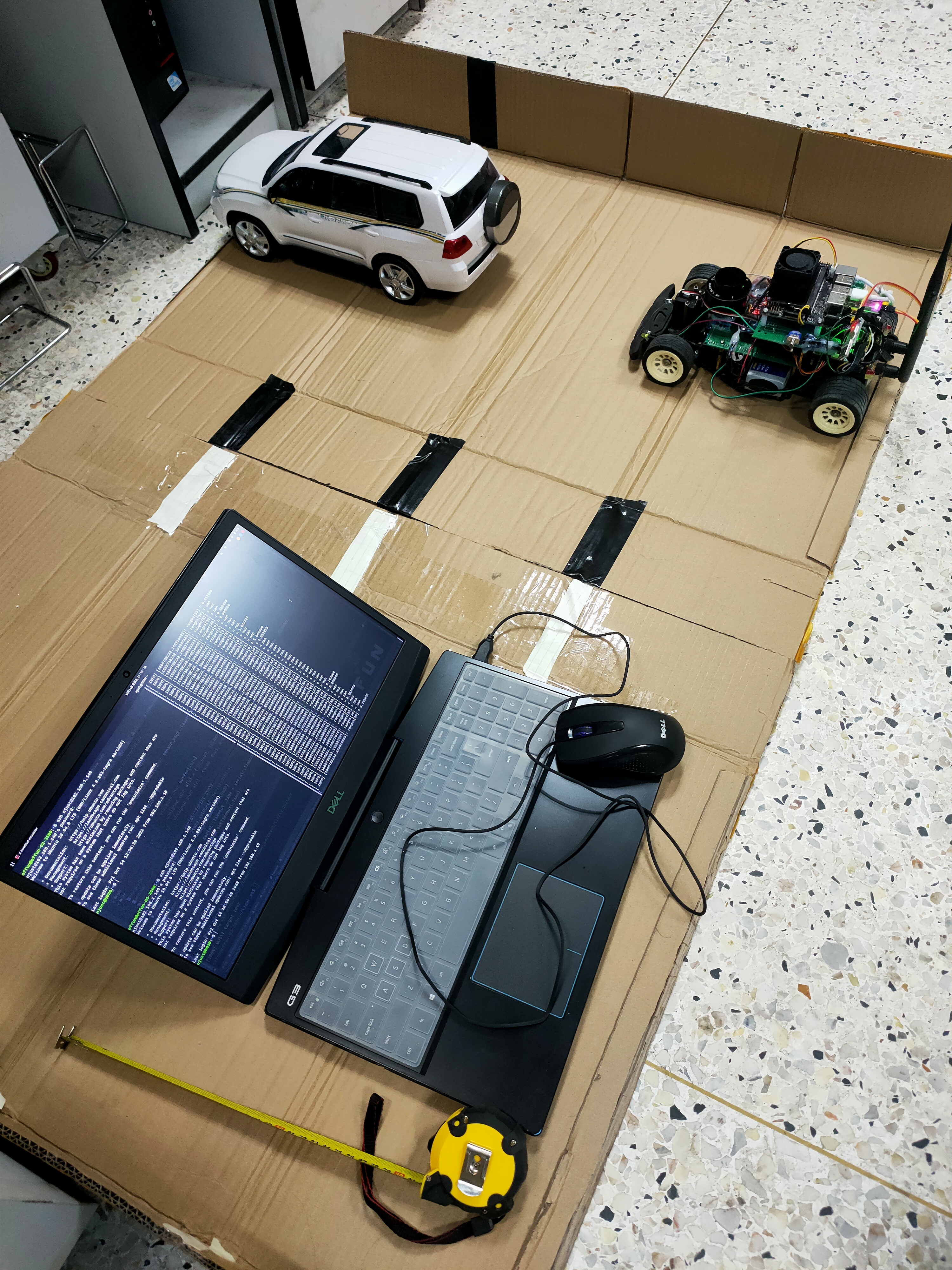
- We used the designed unmanned vehicle platform to participate in the 13th Jiangsu Provincial Robotics Competition’s multi-drone interaction project. The competition simulates autonomous vehicles driving on roads, involving tasks such as straight-line driving, overtaking, lane changing, and parking.
- It was also the final project for a course called ‘Comprehensive Embedded Systems Experiment’ during my master’s studies.
📝 Advisor: Prof. Yifei Wu
📅 Duration: Oct. 2022 - Dec. 2022
Contributions
- Proposed a dual-loop localization and obstacle avoidance algorithm based on LiDAR data for angle and position control, enabling the autonomous vehicle to drive in the center of a simulated road and interact with multiple vehicles.
- Designed a communication program between the NVIDIA Jetson Nano and the lower-level control board based on ROS; integrated all algorithms into ROS packages to improve development efficiency.
- Independently completed the full assembly of the mobile robot.
Outcomes
A complete and versatile development development platform for unmanned vehicle.
A course report that received a score of 93, ranking 1/114 in the class.
Project Showcase
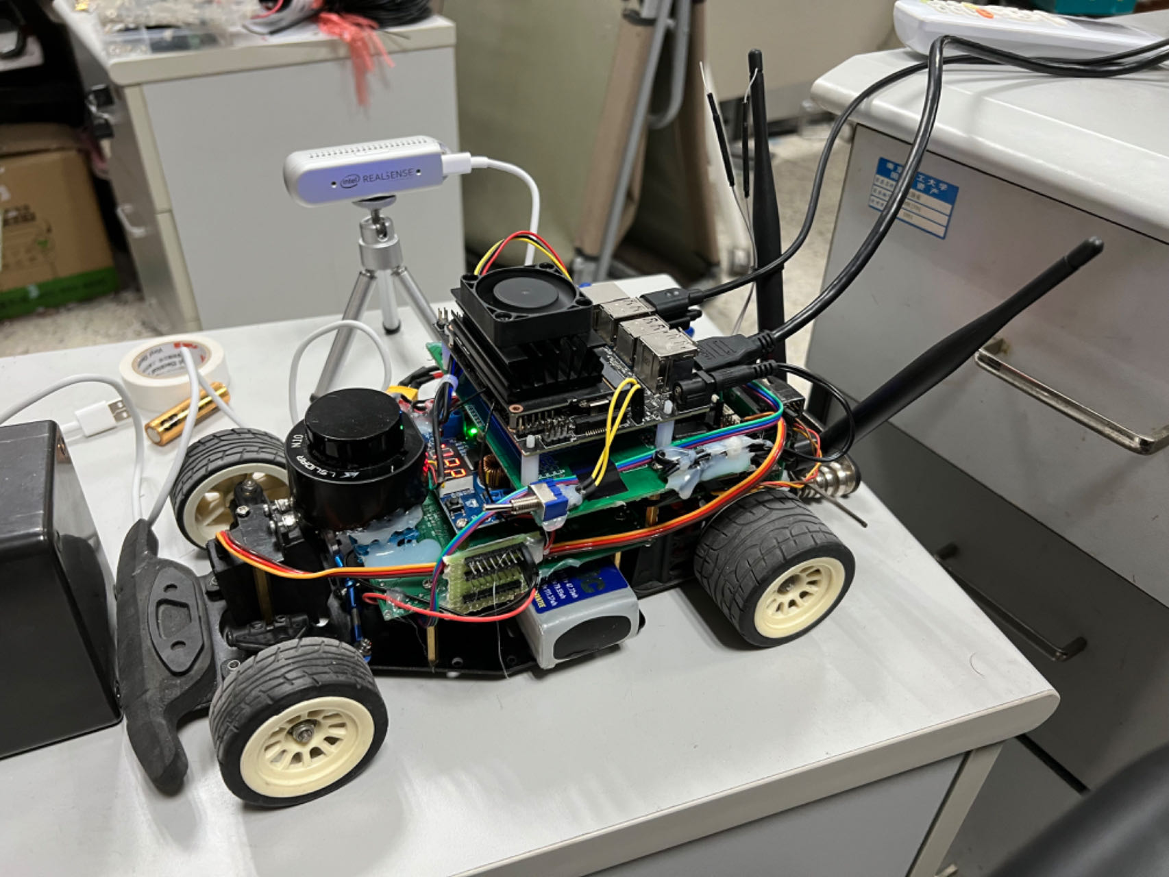
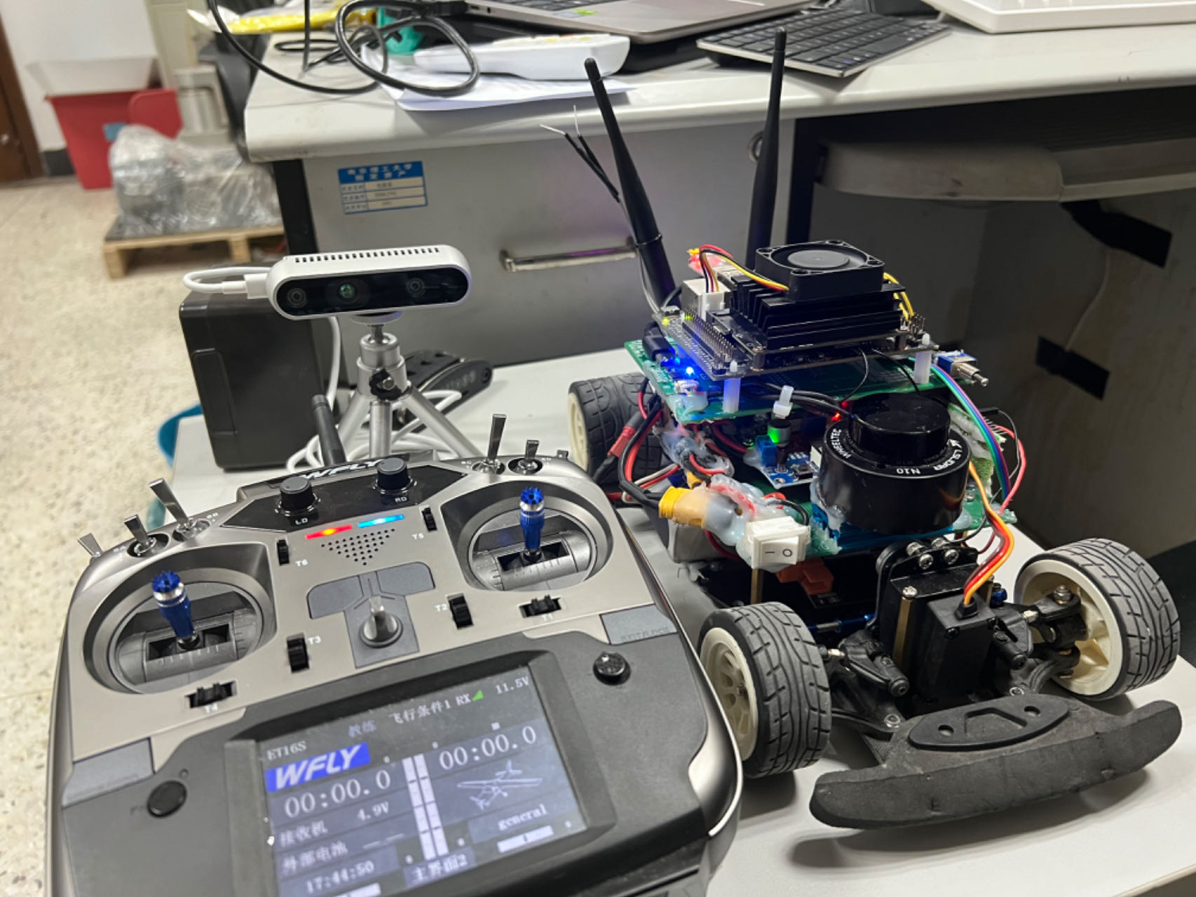
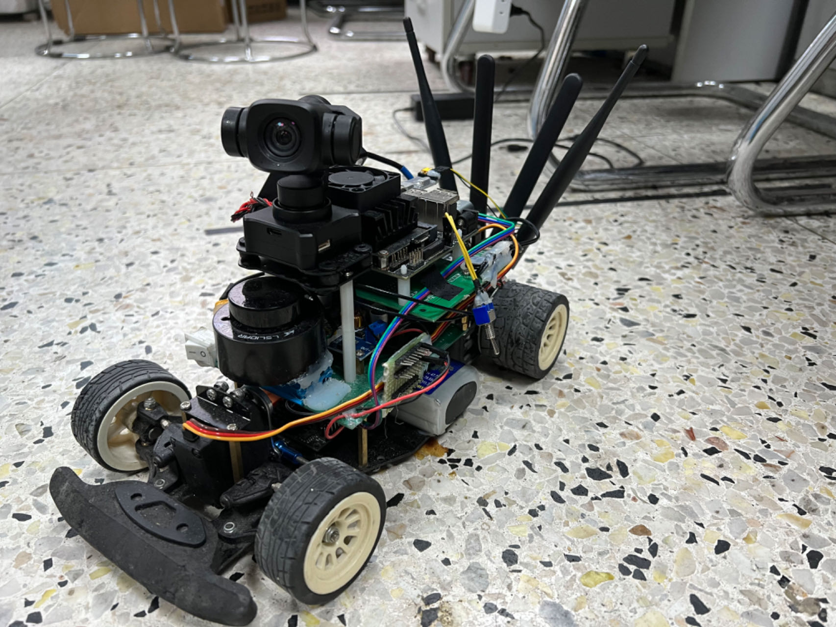
Designed unmanned vehicle development platform:
It comprises of a NVIDIA Jetson Nano, a 2D Lidar, a gimbal camera, a Wifi module, a remoting module and a power module.
|
|
</td>
|
The designed platform can also used to deploy SLAM algorithm:
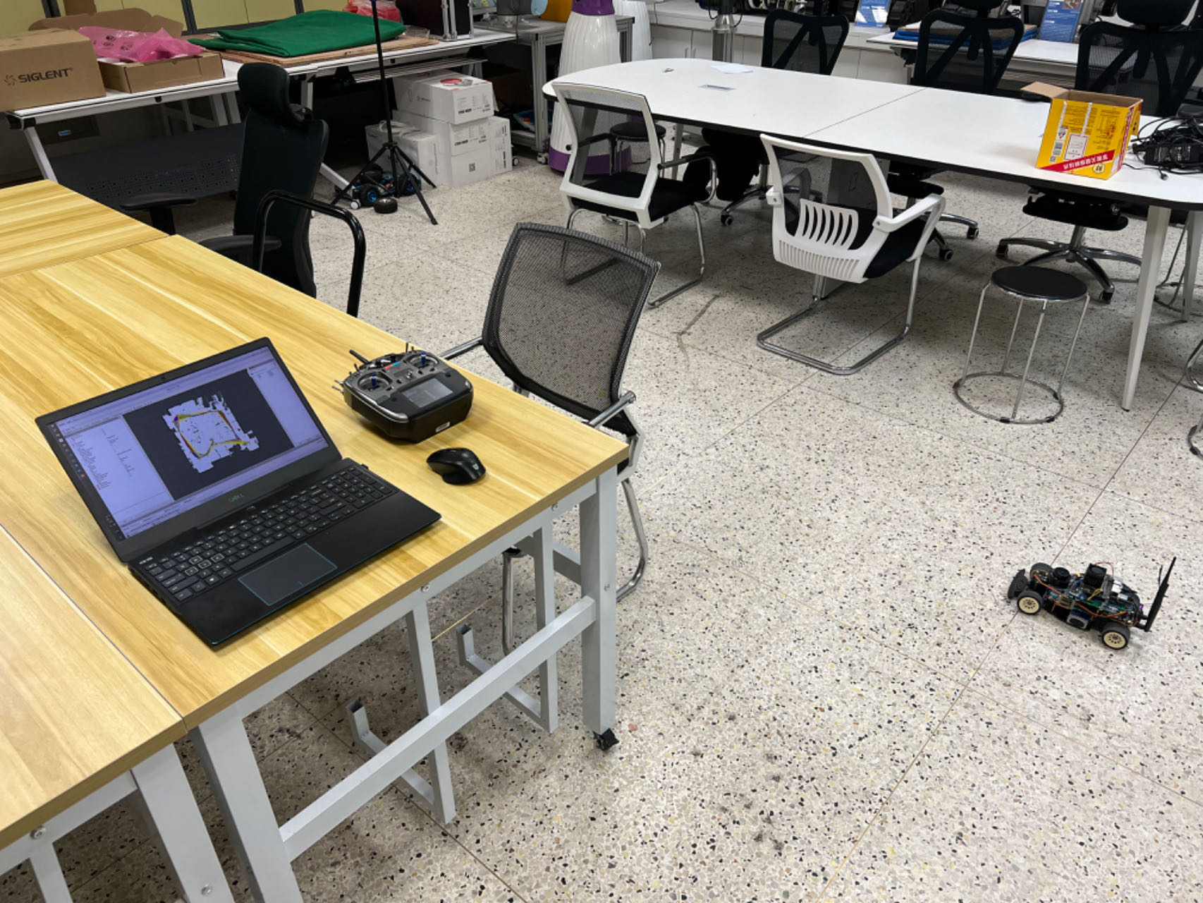
|
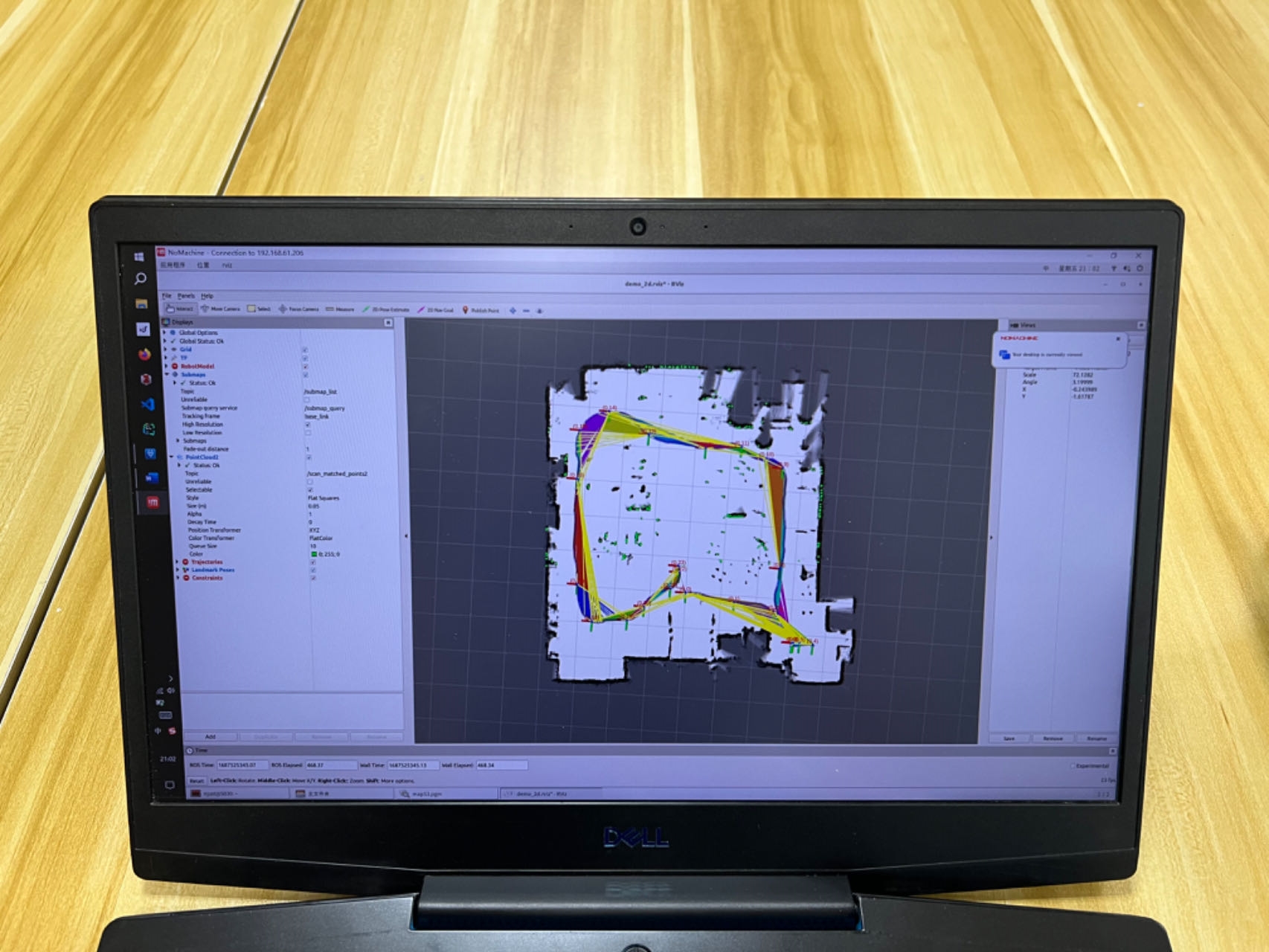
|
Dual-loop localization algorithm based on LiDAR data:
Lidar centre position solution:
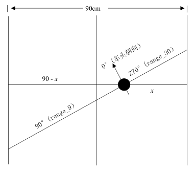
|
By using the distance information at 90° and 270°, the distance $x$ from the LiDAR center to the right-side barrier can be calculated.
For heading control, it is necessary to determine the front-facing direction and the change in orientation of the mobile robot. Since the Ackermann steering mechanism was used in this design, the servo’s steering angle can not directly represent the vehicle’s heading. To address this issue, the design used a trigonometric method to determine the heading.
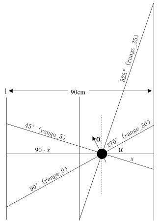
|
$\alpha$ represents the offset angle of the car head. In heading control, the goal is to maintain the angle $\alpha$ at 0°, meaning the vehicle’s front is pointing forward.
The sine of the angle $\alpha$ can be obtained from the following equation:
The block diagram of the heading-position double closed-loop control is shown below:
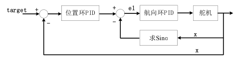
|
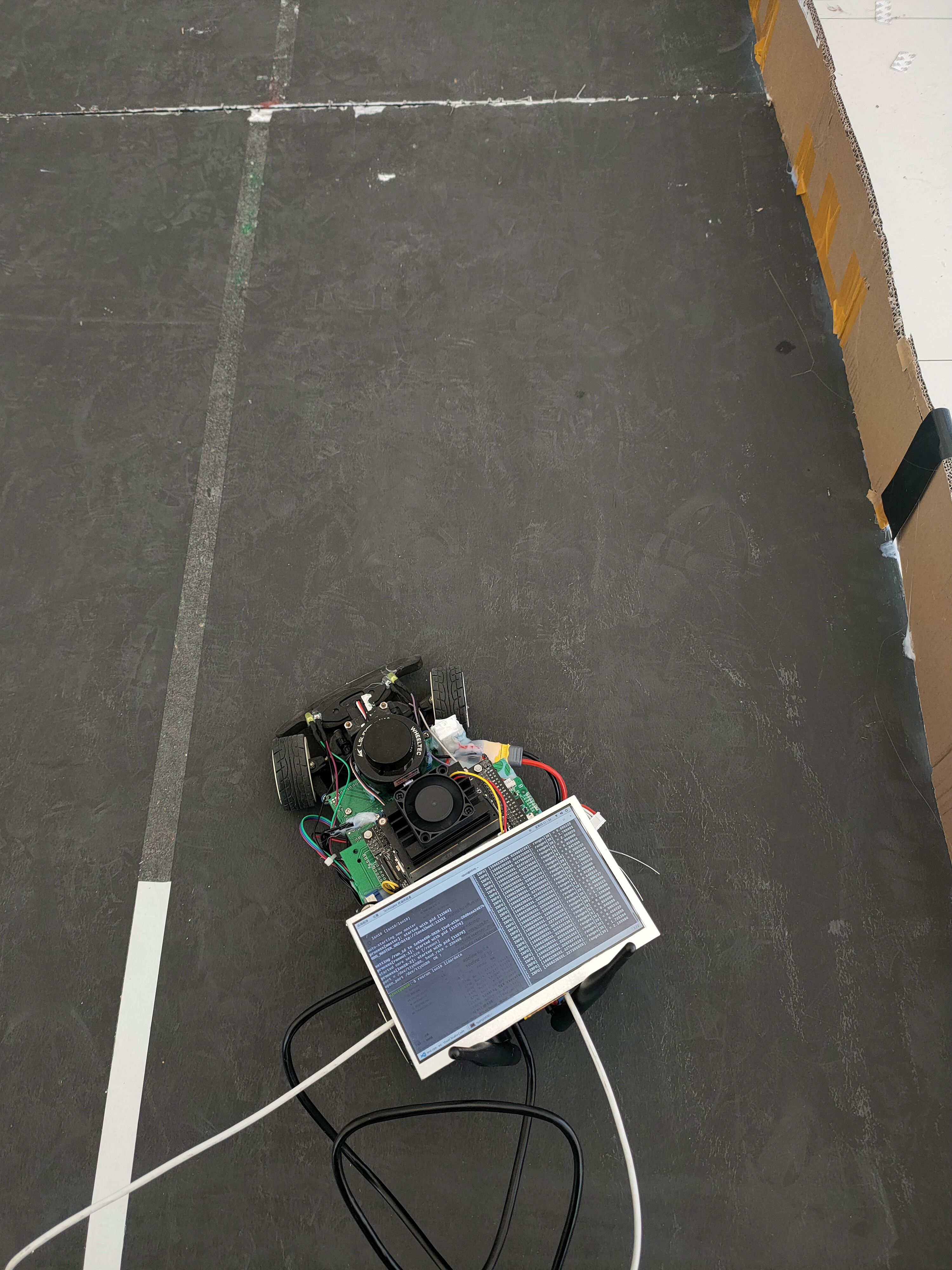
System test:
Test the Lidar data:
|
Test the proposed double-loop localization algorithm:
|